THE
SCIENCE OF BUILDINGS
CURRICULUM
DEVELOPMENT
SECTION 2.0
(*revisions
pending*)
INDEX:
Page:
I.
Abstract 2
II.
Preamble 2
III.
Component
Initiatives 3
IV.
Component Course
Materials 4
V.
Instructional
Strategy 6
VI.
Student
Activities 6
VII.
Assessment Method 7
VIII.
Common Essential
Learnings 7
IX.
Environment 8
X.
Materials and
Resources 8
XI.
Course Text Outline 9
· Science of Buildings 10
· Building Materials 11
· Seasonal Construction 16
· Structural Force Loads 17
· Action and Reaction 20
· Forces on Structural Systems 22
· Structural Frame 28
· Foundation Systems 29
· Floor Systems 37
· Wall Systems 39
· Roof Systems 41
· Building Orientation 43
· Wind Effects 44
· Snow Loads 46
· Exterior Systems 48
· Rain Penetration 51
· Thermal Insulation 53
· Vapour Barrier 56
· Air Leakage 57
· Humidity 59
· Condensation 62
· Sealants 64
XII. New Text Definitions 66
XIII. Appendix 'A': List of Illustrations 67
XIV. Appendix 'B': Bibliography 70
ABSTRACT:
The study of the science of building
provides an understanding of forces at work on structures. Building science
covers all technical aspects of construction from foundations through roofing.
This section also includes discussion on how natural elements and forces act
upon structures. The influences of
landscape design and soil factors are briefly discussed.
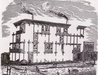
Figure 1: Early Illustration of Steel
(1856)
PREAMBLE:
This section will
provide discussion of the science of architecture relative to construction. A
great architectural design requires effective application during construction
in order to achieve the design goals.
The main goal of this section is to
educate regarding construction techniques, influences and forces at work on
completed buildings. The secondary goal
is to illustrate how building science influences architectural design.
COMPONENT INITIATIVE:
The study of building sciences
incorporates a review of the engineering disciplines that are used to
facilitate the creation of buildings. Buildings defined as Architecture by
Vitruvius within the Section 1.0 – History must contain three elements:
.1 Firmness
(Structure)
.2 Commodity
(Function to serve the user's needs)
.3 Delight
(Aesthetic beauty)
This section provides background for
the study of item #1 – Firmness.
Buildings are constructed for
durability; to endure the affects of time, use and natural elements. The ability to satisfy the need for
durability falls to the realm of building sciences.
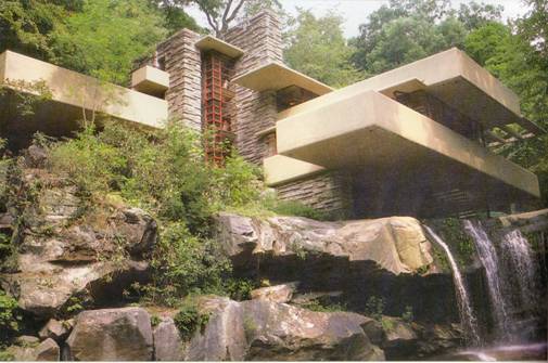
Figure 2: Falling Water, Frank Lloyd Wright (1936)
It is intended that this section
will provide an overview of the elements considered during design and
construction in order to achieve the durability desired for the completed
structure.
COMPONENT COURSE MATERIALS:
The intent of this section is to
provide an understanding of design and construction. Techniques, procedures and
reasons for the way a structure is assembled are reviewed. This section will educate relative to the
reasons why certain items are constructed in certain ways. This section also explores the possible
impact that changes made in design or detailing will have on the final
structure.
Every element of a structure has an
impact relative to the potential for success or failure. The History Section noted one example where
failure came about through the introduction of the end users (Pruitt-Igoe
social housing). That example
illustrated a failure of Commodity, as defined by Vitruvius. Pruitt-Igoe failed to serve the needs of the
end user; therefore it failed its design intent and was subsequently
demolished.
This section reviews potential
impact from construction methods and natural forces. An architect must understand the potential
performance of every building element.
It is with this knowledge that key decisions relative to a structure's
design can be made.
To begin this section, we start by
identifying the five distinct systems for every type of structure. Every building element is present within
these five units. These units do not
include the installed systems providing mechanical (heating and ventilation)
and electrical (lighting and power distribution) services. The impact of these services is discussed
relative to specific details of building sciences only. A thorough discussion of mechanical and
electrical design falls to the realm of the consulting engineers, outside the
scope of this curriculum section.
The five systems of a structure
are:
1.
Structural Frame
2.
Exterior Finishes
3.
Insulated Voids
4.
Vapour Barrier
5.
Interior Finishes
 1. Structural Frame: The bones of the
building, typically erected first. This
item includes foundation and wall/roof systems.
1. Structural Frame: The bones of the
building, typically erected first. This
item includes foundation and wall/roof systems.
2. Exterior Finishes: The visible exterior
surfaces that are applied to the structural frame. This item includes the wall and roof finishes
as well as the foundation finishes. This
item also includes exterior doors and windows.
3. Insulated Voids: The hidden zones,
typically within the structural frame, that are insulated to minimize the
transfer of temperature changes.
4. Vapour Barrier: A hidden item installed
on the warm side of construction insulation materials (the interior side). This item is designed to prevent the passage
of airborne moisture into the wall and roof systems.
5. Interior
Finishes: The visible interior surfaces, applied to the structural
frame. This item includes the basic
materials (drywall, sub-floor, etc) as well as the applied surface finishes
(paint, tile, flooring). This item also
includes interior doors, windows, millwork, and specialties.
A discussion of each of these systems follows within the course text outline.
INSTRUCTIONAL STRATEGY:
Direct
Instruction:
·
Lecture series with written material
handouts
·
Slide presentation showing building science
elements
Indirect
Instruction:
·
Lectures from visiting professionals
·
Audio visual presentations on structures
and design
Independent
Study:
·
Student research on science applications
relative to structures
·
Concept study on architectural styles
related to expression of structure
Interactive
Instruction:
·
Modeling testing on elements discussed
(wind tunnels, expansion testing, failure testing)
·
Site tours of building systems
·
Kinesthetic applications of modeled systems
STUDENT ACTIVITIES:
Oral:
·
Presentation on researched systems
·
Class discussion regarding building
sciences
Visual:
·
Model study of building systems
·
Graphic representation of acquired science
knowledge
Kinesthetic:
·
Participation in modeling testing (loading
and force studies)
Written:
·
Report preparation on model studies and
affects
ASSESSMENT METHOD:
Pencil
& paper method:
·
Written testing: modeling, definitions,
condition assessments
·
Research submission
Performance
assessments
·
Participation in class discussion
·
Participation in group modeling assignment
Personal
assessments
·
Understanding of building sciences
·
Awareness of man-made and natural forces
and their impact
COMMON ESSENTIAL LEARNINGS:
Communication
·
New terminology and definitions
·
Verbal and written skill enhancement
Creative
and Critical Thinking
·
Understanding of forces that affect
man-made environment
Independent
Learning
·
Research and written submission relative to
course content
Numeracy
·
Understanding of load conditions, failure
points and calculated structures
Technological
Literacy
·
Basic understanding of structural concepts
related to buildings
·
Understanding of affect of natural forces
influencing structures
Personal
& Social Values & Skills
·
Enhanced knowledge of relationship between
engineering and architecture
·
Greater understanding of natural forces
within constructed environment
ENVIRONMENT:
Classroom
Climate:
·
Visual access for lecture and presentations
·
Open area for movement during modeling
stage
Physical
Setting
·
Modeling area for natural forces study
·
Seating area for study and research
·
Testing area for viewing and participation
in modeling
Flexible
student groupings:
·
Required for modeling tasks and testing
·
Combination lecture/task format for smaller
group task efforts
Extensions
beyond classroom setting
·
Resource based research
·
Building studies on site (Construction
stage or finished)
Community
experiences
·
Study of projects in progress
·
Study of existing building performance
·
Monitor study of existing building to be
carried out during section term (Study may include student's homes as research
models)
MATERIALS / RESOURCES REQUIRED:
In-room
supplies:
·
Audio visual resources
·
Supplies for modeling studies (materials,
weights and balances)
·
Research stations for independent work
External
supplies:
·
Access to community professionals and
buildings
COURSE
TEXT OUTLINE
SCIENCE OF BUILDINGS
All architectural structure is geometric. It is important in practice that architects have a full understanding of the building sciences. The science of buildings includes:
– structural components
– material components
– ground forces
– water affects (rain, humidity and condensation)
– solar affects
– wind and air actions
– the movement of buildings
Every building is constructed with five principle elements:
1. Structural frame
2. Exterior finishes
3. Insulated voids
4. Vapor barrier
5. Interior Finishes
The structural frame of a building is the first component constructed. This component forms the “bones” of a building. It is often referred to as the skeleton.
The practice of architectural design must consider the materials to be used in the structural framing in order to correctly design and detail a proposed building.
BUILDING MATERIALS
The basic method of construction involves the use of building materials. The selection of specific materials involves four factors - function, material type, environment and economics.
Function is both social (hierarchy, sound) and physical (appearance)
Material Type is the physical and chemical properties of the item.
Environment is the surrounding conditions (temperature, humidity, and location)
Economics is the unit cost of the material as compared to alternate materials.
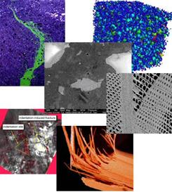
Figure 4: A Wide Variety of Available Materials
There are standard methods of building which are known as accepted practice amongst the industry. These methods would include the “normal” way of wall or roof framing, structural details for foundations, and general installation practices for the miscellaneous components.
The method through which these four factors interact is complicated and varied. Typically, one of the factors will govern the design decision when the overall structure is considered. An example would be summarized by the following consideration in exterior finishes; the decision between brick masonry units or stucco finishes.
· Brick exterior is more expensive than stucco finishes.
· Brick requires additional structural foundation considerations in design due to loading of weight. This fact adds to the cost of foundations, which can impact the overall economics.
· Brick is more durable than stucco.
· Brick presents a different aesthetic than stucco.
· Stucco is more economical than brick.
· Stucco does note require additional foundation design; less cost for foundations.
· Brick moves independently from the back-up material while stucco is applied directly to back-up (wall systems) materials.
· Brick resists changes in temperature and humidity better than stucco. Stucco being a water based materials may break down in high humidity and exposed locations.
· So the debate is seen between the higher cost brick exterior finishes or the lower cost stucco exterior finishes. This example presents only one of the many options and considerations that must be dealt with in designing and detailing a proposed structure.
· The selection of materials for the interior and exterior of a structure must be based on careful consideration of each of the four factors. These factors must be weighed against each other to meet the design intent of the proposed structure.
The biggest factor affecting construction is the conflict between Weather and Building. Buildings must be designed to exclude weather elements such as rain and extreme temperatures, and also to resist the loads imposed by other weather elements such as snow and wind.

Figure 5: Weather and Building
Buildings must be constructed of materials that can resist the deteriorating effects of the weather. There are three basic elements that affect the long term performance of a structure. These elements are temperature, precipitation and wind.
1. Temperature
The resistance of the walls to heat transfer and the capacity of the heating system will depend on the temperature difference that must be maintained between the inside and outside of the building. Inside temperatures are likely to be constant due to the mechanical heating systems installed while the outside temperatures vary widely over a span of 50 to 60 degrees Celsius.
Extreme variations may occur in specialty building such as arenas, swimming pools, museums and so on. Each structure has to be reviewed relative to its special needs.
.
2. Precipitation.
Precipitation is one item that can never be ignored. Precipitation includes rainwater and snowfall. All roofs and walls must be designed to shed rainwater without allowing extreme loads. The structure must be able to withstand the additional seasonal weight loads of snow in our country. (This item is typically shown on the structural construction drawings as a graph or highlighted zone.)
3. Wind
Wind involves both movable air (traveling wind) and barometric pressure air movement. Air transfer from and through structure happens because of interior and exterior air movement pressure.
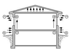
Figure 6: Wind Force Reactions
The amount of warm air that escapes through cracks around doors and windows and the amount of cold air or dust that gets in depends on the wind speed and the relative difference in pressure between the structure and the exterior.
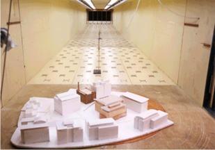
Figure 7: Wind Velocity Tunnel Testing
Buildings are typically pressurized by the mechanical air handling system which causes air to flow out through openings and cracks. Less pressure on the exterior will allow more building pressure air movement to escape. Higher wind speed will create higher pressures both on the windward and the leeward side of a structure. Wind pressure is also responsible for the chimney or stack effect that many buildings experience.
Seasonal Construction
The conflict between weather and building continues throughout the year, being a concern in all seasons. Typically, it is thought that summer construction is preferable to winter however that may be only from a control perspective of the contractor.
Winter construction is a fact in Canada. It is desirable on any building project to have the outer shell and cladding installed (close in the building shell) before cold weather hits. There are added complications in winter construction due to frozen excavations, additional hoarding and heating (protection for concrete curing and exterior finishes) and additional heat is require to facilitate interior finishing. The selection of materials is a consideration due to these factors. Steel installation has a winter advantage to masonry load bearing walls since steel can be erected outside without the need for hoarding and heating. (Just don’t stick your tongue on it). Pre-cast concrete structural wall systems are another cold weather option. Pre-cast units provide factory fabrication, quality control and ease of installation regardless of the exterior temperatures.
The debate between summer and winter construction effects continues. Heated hoarding offers control of interior temperature while summer construction does not. Heating systems, usually open flame propane fired unit heaters produce a lot of moisture which may affect the finishes. Typical summer construction projects allow for open air ventilation without running any additional heat units. This method, while comfortable, can allow for extremes in temperature due to ever changing wind/rain conditions, without any internal method of control in the building.
The season in which the construction process will take place must be considered when the architectural design process is underway.
Structural Force Loads
Structural framing in building systems must take into account the forces that will affect a building. Force on a building structure can come in many ways such as:
– dead load of the structure
– dead load of the finishes
– live load of occupants and furnishings
– external forces (wind, rain, etc)
– snow loads
– ground force loads.
Figure 8: Structural Loading Diagram
An explanation of each force type is.
1. Dead load of structure: the weight of the structural materials themselves must be the first consideration. Horizontal structural members such as beams, joists, and trusses must be able to support their own weight.
2. Dead load of the finishes: the weight of exterior and interior finishes must be calculated for the sizing of the structural system. For example: the use of brick adds a great deal more weight to the overall building as opposed to the use of stucco.
3. Live load of occupants and furnishings: structural systems must allow for calculated limits of additional weight added to an empty building. The weights of furniture, file cabinets, computers and even people must be factored into the calculations for structural systems.
4. Wind forces: wind action on a building will cause two reactions on the building walls. The side that faces the wind will be subjected to compression, due to the wind pushing on the exterior walls. The side that is away from the wind direction will be subjected to tension. This tension is due to the negative pressure created by the wind as it rushes by. This force will cause the wall on that side of the building to try and pull away, pulling on the structural frame.
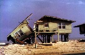
Figure 9: Hurricane Damage, Florida (2004)
5. Snow
loads: design for building systems
in
6. Ground force loads: these loads affect the foundation of a
structural system. The earth constantly moves
around all foundations. These shifts may be caused by seismic activity
(earthquakes) or by moisture.
Earthquakes are not common for our region of
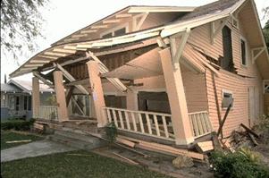
Figure 10: Earthquake Ground Force, California (2004)
Action and Reaction
The forces that affect structural systems are opposites known as ‘action’ and ‘reaction’. Action causes a structural member to change its shape due to the force (weight or load) applied to it. When a load is placed on a beam, the beam will sag down. This load is the ‘action’ on the beam. This load may either be a dead load (part of the permanent structure or building system), or a live load (use of the building or natural elements such as snow, wind or rain).
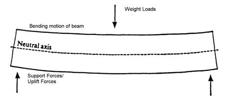
Figure 11: Action and Reaction Diagram
Reaction is the force that causes a structural member to return to its original shape once the load is removed. Reaction is only active relative to live loads in a building. The dead load of a building is permanent, therefore the structural design of the system must allow for the dead load action to occur during construction.
The forces that generate action on a structural member have three components:
1. Magnitude: the overall power or strength of the force.
2. Direction: the direction in which the force travels while affecting the structural member.
3. Position: the location of the force as it contacts the structural member.
These three components can create many different actions on each individual structural member. A light force traveling into the structure near the connections will have far less impact than a strong force traveling into the structure at its midpoint.
 Figure 12: Force Location Factors
All magnitudes of forces must be calculated to accurately design the structural components of a building.
When structural members move in reaction to forces applied, it is called ‘deflection’. A structural member that is forced beyond its deflection limit will not be able to react enough to return to its original shape. These structural members have now experienced ‘failure’, and they will no longer be able to carry the loads required.
Structural failure means that the damage will not self-repair. It is likely that additional damage will occur since structural members that have failed will not be able to carry even the original loads. It is for this reason that roofs can cave in under heavy snow loads, connections can tear out thus loosening the system under wind loads, or systems may fail outright if overloaded through live loads.
Forces on Structural Systems
A beam is the simplest structural member to review for this section. As a force is applied to the beam (in this example, the force is located at the midpoint), the beam must change its shape to accept the action of the force. The beam will bend.
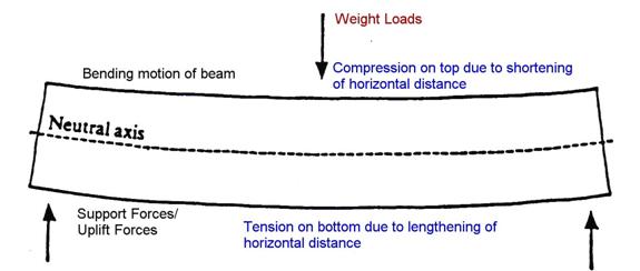
Figure 13: Tension and Compression
The bending motion of a beam presents two different types of structural movement. The top surface of the beam is subjected to “compression” as the horizontal length is shortened. The bottom surface of the beam is subjected to “tension” as the length of the beam is stretched. Tension and compression are opposite reactions, both being experienced by the beam under a load force.
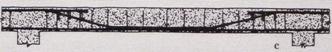
Figure 14: Concrete Beam Section
Concrete is a perfect material for compression since its mass allows it to carry heavy loads. Concrete is a poor material for tension since the material does not stretch. It has no capacity for expansion. The addition of steel into concrete forms corrected this deficiency. Steel encased within the concrete form will allow greater amounts of tension to be applied than concrete without steel can handle. It is for this reason that the Industrial Revolution changed the nature of concrete by providing easy access to steel which was included in the concrete form.
The arch form, mentioned in detail within the History Section, is another example of the differences between compression and tension. Bricks and masonry units function in a way similar to concrete. Masonry is an excellent material when subjected to compression but a poor material for tension. There is no easy way to tie the many individual bricks together that would allow for tension forces.
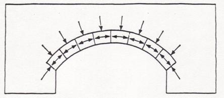
Figure 15: Forces acting on an Arch
The arch method of construction was based on the theory of compression. Masonry was stacked over a wooden form up to the ridge or peak of the arch. At the peak, a triangular-shaped masonry unit would be installed to tie both sides of the arch together. The compression force was therefore distributed equally on each side; the whole assembly held together by its own weight. If you were to remove the keystone from the top centre position and the sides would cave in.
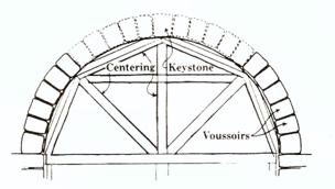
Figure 16: Arch Construction Sketch
The sides of an arch are also subjected to outward forces. The weight and loading of the arch will create a force that pushes outward at the base of the arch form. The walls at the base of the arch must be strong enough to withstand this force. It is for this reason that early history arch walls were very thick. The thickness of the wall was in proportion to the span and height of the arch. A wide span meant a tall height, which creates extremely strong forces at the base.
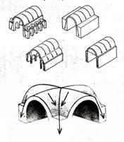
Figure 17: Forces on Vaults
The use of buttresses (flying buttresses in Gothic structures) was designed to react to the force of the roof arch. The buttress is a brace on the wall, connecting at the base of the arch. It is these elements which react to the force load. By using buttresses to take on some of the force, designers were able to thin the wall down. There would be less force from the arch action on the wall system; therefore less strength was required in the wall itself. The decrease in required strength meant that a thinner wall could be used.
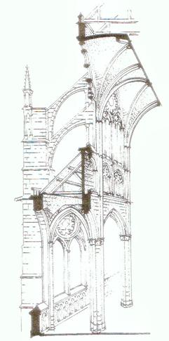
Figure 18: Wall Systems, Amiens Cathedral
Truss systems are designed to act in the same way as our earlier example of the beam. Trusses have top and bottom pieces along their length, known as chords, which counteract the forces applied. Trusses also have individual pieces between the top and bottom chords. These pieces, known as the webs, assist the chords in properly distributing the force loads. Distribution of the load is important to ensure that no one piece or member is subjected to a load beyond its capacity (strength).
Figure 19: Truss System
The roof system is generally made up of roof trusses bearing on the wall or support frame. Roof trusses may either be constructed of wood or steel. It may be flat (as seen on commercial buildings) or sloped (small commercial or residential buildings).
The triangular shape is one of the most stable geometric forms, consistent in distribution of loads. The triangular shape is used extensively in truss construction.
Trusses are constructed using linked or connected triangular shapes to provide great strength and light weight. Great strength is required in order to span the open distance (unsupported length). Light weight minimizes the “dead load” of the truss itself, allowing for easy installation and stronger support strength.
Roof trusses are subjected to loads from the exterior such as wind, rain and snow. These trusses are also subjected to temperature changes depending on the insulation location.
Structural Frame
The structural frame of a building is made up of:
· Foundation systems
· Floor systems
· Wall systems
· Roof systems
These four sub-systems act together to create the structural shell of every building. It is not necessary to have any of the other four basic building elements (exterior and interior finishes, insulation, vapour barrier) installed for the building to stand on its own. A structural shell is self-supporting, though unfinished.
An example of this definition was seen in the Saskatchewan Centre of the Arts. The building frame was erected a full two years prior to completion of the interior. The steel frame was left exposed due to funding difficulties for 18 months. This exposure gave the frame the nickname of “world’s largest monkey bars as it stood unattended.
The first of these sub-systems is the foundation system.
Foundation Systems
Foundation systems are the bottom level of structure that connects to the earth. The action of transferring building weight through to the soil is known as the bearing condition. Building forces are transferred through to the earth by the use of piles or foundation walls with footings.
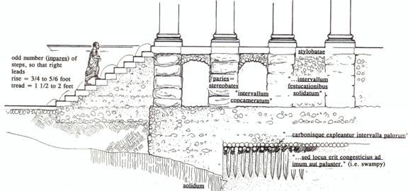
Figure 20: Ancient Greek Foundations
There are many types of piles and installation methods available. A geotechnical engineer is required to drill the soil of the building site. They remove samples of the soil and test to determine the soil's capacity to carry the building weight (loading). The foundation system used is based on the engineer's recommendation. Pile bearing conditions may either be end bearing or skin friction type.
End bearing piles act like columns buried in the earth. These piles carry the building loads straight down to the bearing level of the soil.
End bearing piles have several options for use. They may be designed as:
1. Post and pad type: This type is similar to that used in the middle of residential basements and shallower commercial crawlspaces. A concrete pad is poured with the pile resting on the centre of the pad. If you think of the posts in the middle of your basement, you can imagine the structural pad beneath it.
Foundation walls are similar to post and pad pile types except that foundation walls provide a continuous pad (footing) supporting a continuous wall (foundation wall). These systems rest directly on compacted undisturbed soil.
Figure 21: Belled Pile
2. Bell piles: This type of pile drills a shaft similar to skin friction pile types. The bottom of the shaft is augured out in the shape of a bell. This method allows the load to spread out over a greater surface area than just the shaft. Back in the old days, the only way to inspect a belled pile was to lower the inspector down the shaft with a flashlight. Inspections today are much easier using remote camera drops.
Skin friction type piles use the natural force of friction on their sides to transfer out the building loads. Imagine being squeezed at the shoulders and lifted up that way. You would be suspended but your legs would remain free. This method is how skin friction type piles work.
Skin friction piles depend on the consistency of soil along the vertical length of the pile shaft. There are several options for use relative to friction type piles including:
1. Driven timber piles: This type of pile drills a small hole for guidance first. The actual pile resembles a telephone post, both in width and often length. The pile is centered above the guide hole and then hammered into the ground by a mechanical press.
Figure 22: Skin Friction Pile
2. Cast-in-place concrete piles: This type of pile drills a hole the diameter of the intended pile. Steel reinforcing cages are suspended in the hole with concrete poured down the full depth. This type of pile depends on the finished concrete bearing on the side soil pressure of the pile length.
Architectural design must consider the proposed foundation system type due to the ability to carry the intended building loads.
Early history construction built foundations suitable in width for the assumed loads of the proposed building. Structural or civil engineering as a science did not come into existence until the nineteenth century. Building prior to the science was based on experience and assumption.
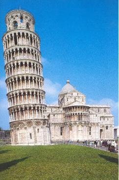
Figure 23: Bell Tower, Pisa Cathedral (1063)
The Leaning Tower of Pisa (Campanile of Pisa Cathedral) is the best example of foundation system failure. The soil conditions are not able to carry the weight of the structure resulting in the uniform shift of the building’s foundation sufficiently to cause the tilt.
All foundation systems are subjected
to ground force loads.
Settlement will take place in both
mechanical / electrical trenches as well as around the building
excavation. Settlement factors can be
calculated however there are cases of the extreme taking place. Parts
of central Mexico City have settled more than 10 feet in this century.
Figure 24: Potential Foundation Failure Points
Foundations will be subjected to both settlement and expansion. Frost can damage building foundations, retaining walls, driveways, walls and similar structures. Frost occurs in soil due to the moisture in the soil freezing solid. This action will cause a heaving affect which can crack foundation walls. Frost penetration into the soil must be taken into consideration and allowances made in foundation design to compensate for it. Heaving pressures decrease in keeping with moisture content. Warm buildings typically keep the soil warm due to heat escaping through the foundation and therefore no or little heaving occurs. Cold structures are more susceptible to heaving which may occur during construction.
Foundation movement
There are basically three types of settlement categories:
Uniform - settles straight down
Tilt - settles intact but on an angle
Non-uniform- settles at varied angles
While all of these types are damaging, the non-uniform type will cause the most stress on a foundation structure.
 Figure 25: Three Types of Foundation
Movement
Figure 25: Three Types of Foundation
Movement
Landscaping is another factor that may affect the foundations of structures. Trees are a beautiful landscape feature however trees need water. They will extract it from the soil immediately adjacent a foundation, causing shrinkage and cracking in the surface and a loss of strength in the soil. Drying out soil will tend to settle while efforts to keep landscaping watered may cause the ground to swell due to high moisture content.
Though they don’t look overly cumbersome, trees can be deceiving. A little more than 10% of a tree’s wood mass is underground in the form of roots. Oak tree roots add up to hundreds of miles when measured. The spread of tree roots is sometimes extreme wherein roots can spread over 100 feet from the tree. The effects and placement of landscaping as indicated on the site or landscaping plan is something that needs careful consideration.
Floor Systems
The second sub-system noted is Floor Systems.
Floor systems are the structural components that provide the working surface of the building. Floor systems may be constructed either of wood, steel, or concrete, similar to foundation systems. Wood construction is typically used in most residential and light commercial construction. Steel and concrete, or mixtures of the two, are typically used in industrial, commercial and institutional construction.
The choice of floor systems is a critical decision to be made at the outset of a project. The design for any structure must take into account the floor system type and its potential affect on the overall structure. Reasons for selection of a specific floor system type may be:
· economics: the lesser cost system depending on the application
· height restrictions for multi-storey buildings
· mechanical systems to be integrated into the floor
· season of construction
· availability of labour forces and relative skills
· overall size of the intended structure
· overall scale of the intended structure
These reasons illustrate a few of the many considerations relative to floor systems.
The basic engineering of a floor system is similar to that which is applied to wall and roof systems. The main difference is found in the fact that floor systems are not subjected to weather or natural forces as wall and roof systems are.
Floor systems are engineered using a spanning element (floor joist or beam system) topped with a membrane (plywood, metal deck/concrete, or concrete slab). The spanning element provides the basic carrying capacity of the floor system. These elements are designed to carry the bulk of the intended loads (dead load and live load).
The membrane applied to the top of the spanning elements is used to tie all of the individual pieces together. This method of tying the joists together creates what is known as a ‘diaphragm’ system. The membrane takes the initial loads applied and transfers these loads into the spanning elements. The spanning element then transfers these loads down through the main structural frame.
The critical assembly includes all of the noted pieces – membrane, spanning element, and structural frame. Each of these items is required to create the rigidity of the structural floor system to hold up the intended users and equipment, as well as interior wall systems.
Wall Systems
Wall systems act in a similar fashion as floor systems. Wall systems used to carry structural loads are called “bearing walls” since these systems bear the weight of the elements above. Wall systems that are installed only as infill, not carrying designated structural loads, are called “non-loadbearing” walls.
The spanning element of a wall system is called the stud. These studs may be wood, metal, or even masonry, depending on their use and location.
The membrane used in stud wall systems is the plywood sheathing, typically installed on the exterior side of the building.
These two elements (studs and plywood) act in a fashion similar to the floor system. The sheathing accepts the majority of the applied horizontal load; the studs accept the vertically-applied loads. Together, the combination creates a diaphragm of strength and rigidity.
Exterior wall systems are subjected to a variety of forces including:
· applied structural loads,
· outside force loads of wind and moisture.
The type of exterior wall system used for any specific project depends on several factors:
· economics – depending on budget & specific installation
· force loads – applied loads and natural forces
· desired interior finishes - required finishes as determined via consultation with the client. Some installations may require the specific durability offered by concrete block. Some installations may have a specific insulation value required which would determine the wall system type
· desired exterior finishes - this element is tied into the economics of the project as well as the durability required
Interior wall systems which are designed as bearing types are subject to the same considerations as the exterior walls (economics, durability, finishes). The exception for interior wall systems is that they are not subjected to external forces (wind and natural elements).
Roof Systems
Roof systems are in the same category as floor systems for spanning elements and membrane.
Roof systems differ from floor systems as they are not subjected to the same loading as floor systems. Typically the live-load for a roof system does not have to consider occupants and furnishings. (Roof systems designed as patios and decks do consider occupant loads).
Roof systems contain the same elements as floor systems – spanning elements and membrane. The added consideration for a roof system is its ability to contain or carry insulation types, and exterior protection.
Roof systems are similar to wall systems in the way they are subjected to external force loads – wind, rain/water, and snow loads. Roof structures can be subjected to extremely powerful force-loads applied by high winds (positive and negative pressures), extremes in rainfall (torrential downpours), or heavy snow loads. These forces have been well documented in their power to cause the collapse of a roof structure.
Roof systems may differ from floor systems in their basic design shape. Roof trusses provide a pitch or slope to the roof which carries water away from the structure and directs winds over it. Though the trusses may be sloped on top, and even the bottom, they are still designed as the spanning element of the roof system. The membrane (sheathing) is used to tie the trusses together to form the diaphragm.
Roof systems may be designed as “flat” roofs as seen on many commercial and institutional structures. Flat roofs are not really dead level since a minor slope (1/8” per foot) is provided either through installing the structure on a sloped deck or by using sloped rigid insulation. This minor slope facilitates the drainage of water through either perimeter eavestrough or internal roof drains.
Flat roofs are subjected to heavier water/snow loads than pitched roof systems. Pitched roof systems are subjected to stronger wind-force loads than flat roof systems.
Special conditions may exist on a
project that would require a heavier roof system than one would
anticipate. The RCMP Detachment building
located at the
The structural frame forms the basic component of every building. Each element noted must act according to its own function and also in accordance with the function provided by the whole assembly. A structural system with any one weak point may be subjected to premature failure.
All individual items must act alone and must act together. It is in this manner that the structural steel can be self-supporting.
The external forces acting on the exterior finishes and structural frame vary depending on the building’s location, site, and specifically its orientation.
Building Orientation
The orientation of a building will play a large role in the amount of movement the wall and roof systems will be subjected to. Temperature variations between building sides can vary from 65 degrees Fahrenheit in summer to 81 degrees Fahrenheit in winter. These variations in temperatures can lead to accelerated freeze thaw cycles during the spring/fall seasons as surfaces become warm, and then cool with condensed vapour that can freeze overnight.
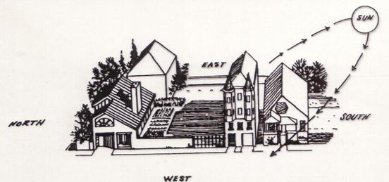
Figure 27: Solar Orientation
Another factor that is affected by orientation of the building is the wind direction. Northwest winter winds are fairly common which will cause negative pressures on the southeast sides leading to increase exfiltration and condensation in the wall and roof systems.
Wind Effects
Wind pressure on a building is referred to as a live load on the systems. That means that it varies within known limits but is not a constant. This is significant due to larger number of high rise buildings where the wind pressures can become quite extreme. Tall buildings extend into regions of high velocity air movement which will cause excessive swaying in strong winds.
Wind can have an equally destructive effect on smaller buildings. Entire roof systems can be lifted off either by positive pressure of wind getting under the system (metal roof systems) or negative pressures of the wind above a poorly anchored lightweight roof system. Typical damage and wear on roof systems is usually confined to small sections at corners and ridges. A further concern with wind is the uplift that it can apply under exposed canopies or open structures.
Figure 28: Wind Affects
Wind Pressures will cause structural loading as well as contribute to other affects on the exterior finishes. Masonry walls may be displaced by ice in the wall as a result of moisture exfiltration under negative outside pressure. Rain leakage around flashings and through joints in curtain walls may caused by a pressure gradient across the wall. The building ventilation system may be affected due to air starvation or too much pressure on the grilles.
Wind is also responsible for the snow drifting that typically occurs on Canadian buildings.
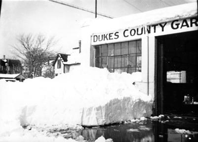
Figure 29: Blown in Snow Drifts
Snow Loads
Snow loading is a very serious
concern both from a structural and architectural perspective. The amount of snowfall varies across

Figure 30: Snow Load Diagrams
Exterior Systems
Exterior systems refer to the items installed around or in front of the structural frame of a building. The structural frame is occasionally installed on the exterior side of the building, leaving it visible, as can be seen with several ‘high-tech’ buildings but that is not the norm.
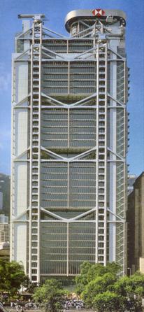
Figure 31: Hong Kong Bank Building, Shanghai
Structural systems installed on the exterior are subjected to all of the considerations noted earlier. Exterior structural systems are also subjected to movement due to temperature changes. Steel expands as it is warmed. Steel contracts or shrinks as it cools. The amount of movement in imperceptible to watch but it can be sufficient to cause dislocation of connections in the systems. Exterior structural systems must be able to withstand movement generated by an 80 degree Celsius change in temperature (+40 degrees to -40 degrees)
The main functions of the exterior systems can be summarized by the following list:
1. Control heat flow
2. Control air flow
3. Control water vapour flow
4. Control rain penetration
5. Control light
6. Control noise
7. Control fire
8. Provide strength and rigidity
9. Be durable
10. Be aesthetically pleasing
11. Be economical
The effectiveness of these items varies due to the actual materials and installation method. Concerns must be reviewed relative to the connections between dissimilar materials and also relative to the overall size of the plane of materials. This size concern relates specifically to movements in wall/roof planes that can cause breakage or cracking of the surface finish or substrate.
Dimensional changes may result from changes in moisture content in materials, aging or degrading effects of the environment. Cracks in the surface material lead to water infusion into the system (a forerunner to freeze/thaw in a system) or exfiltration from the building which can lead to condensation in the wall/roof systems.
Materials don’t require a great deal of force to cause a shift and crack. A strain of only 0.01% is required to cause a “failure” in normal/plain concrete. This strain amount can be produced by a temperature change of only 20 degrees Fahrenheit (11 degrees Celsius). Failure in this scenario relates to cracking or fissures in the surface material.
Concrete blocks shrink up to 0.04% while the typical exterior brick veneer is known to expand with moisture. These percentages are not major however they can add up quickly when dealing with multiple stories.
The basic fact of materials is that they will expand when warmed and contract when cold. This is typical for all materials, even human skin. There may also be movement due to increased or decreased moisture content of a material. This action is typically seen in wood members.
The first point of containment is to restrain the movement of the material. Fasten it down so it won’t go anywhere. The problem with this solution is that it may result in cracking, twisting or warping of the material to a state that it won’t rebound from. This isn’t always the best possible method to solve the problem.
Accepting the fact that materials will move throughout the lifespan of the building is a fact of construction. Methods to contain the amount of movement are included in every project.
The basic method for containment is to provide control joints at regular intervals. Control joints are breaks in the material plane that are filled with sealants or reglet material to allow for calculated movements. The fact that a plane of materials is broken into sections by pony walls or even sealants allows the opportunity for moisture to penetrate the wall/roof system.
 Figure
32: Expansion Joint Detail for Roof Systems
Figure
32: Expansion Joint Detail for Roof Systems
Rain Penetration
The presence of excess water is a key factor in most cases of wall or roof system deterioration. Water is most likely to penetrate systems due to the force of rain. There are several different forces which can contribute to infiltration:
- Kinetic energy - This is the wind driven rain type that forces water through cracks in the system.
- Suction - This method is caused by a pressure drop in wall/roof system which creates a negative pressure on the interior of the building.
- Gravity - Self-explanatory. Leaks happen through cracks in the system caused by past movement.
- Air pressure -This method is similar to Suction in that pressure changes between interior and exterior can fluctuate wildly, especially during a sudden rain storm. The difference in pressures around a building allow for water to come in at low pressure points. Movement in the wall system may open up sealant locations, creating a new point of entry for the water.
Figure 33: Vertical Air Pressures
The basic thrust of a wall system should recognize the fact that water will enter it at some point. It is important to allow water in and give it a way to get out. This idea can be seen in the weep holes used in masonry construction. That is why weep holes must be kept clean.
The use of a “rain screen” system recognizes the presence of water in the atmosphere and allows for it. A rain screen is like a false front to a building, being the cladding in front of the main wall system. This system equalizes the pressure behind the exterior skin by allowing air to travel through it while protecting the insulated sections from immediate impact damage. This system leaves the thermally insulated/vapour barrier section intact.
Thermal Insulation
Thermal insulation is used in buildings to provide resistance to the flow of heat. Its basic benefits are:
- reduces heat loss in winter
- reduces heat gain in summer
Typical insulation installation methods are:
Wood / steel frame walls - between framing members
Masonry walls - in cavity space.
Insulation allows for a moderate change in temperature of the materials it may be attached to. The moderate temperature fluctuations will contribute to minimal movement of the materials, thereby decreasing the overall requirements to control cracking and deflection.
The following page shows two wall systems with the insulation located at two distinct spots; one on the exterior and one on the interior. It is important to note the temperature variations that the concrete block wall system is affected by.
In Wall No. 1 the temperature limits between summer and winter are extreme due to the insulation on the interior side of the wall system.
In Wall No. 2, the temperature limits are minimal due to insulation on the exterior. These factors must be considered when construction occurs.
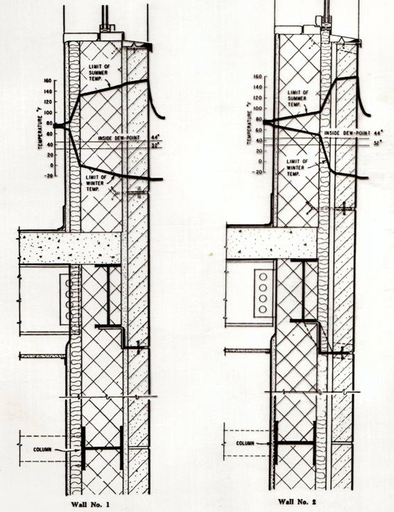
Figure 32: Thermal Diagrams
Insulation is great stuff however it performs only as well as was installed. A lack on installation talent on behalf of the installer can create performance problems that are a nuisance and may result in increased maintenance. Where high humidity levels are going to be present, proper insulation can prevent surface condensation on walls, ceilings and floors. Poor continuity in the insulation performance results in temperature differences between materials, possibly causing condensation. Too many gaps between the insulation and the actual framing can reduce the effective insulating value to nil.
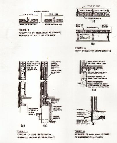
Figure 33: Insulation Diagrams
Vapour Barrier
A vapour barrier refers to any material used to restrict the movement of water vapour into a wall or roof system. The possible entry of water vapour on the interior side should be restricted and freedom for it to escape on the cold side facilitated. Vapour barriers are a special class of materials which offer high resistance to the flow of water vapour. A vapour barrier will only reduce the amount of moisture entering the wall system from within the building. It is never assumed that it will restrict the movement of moisture entirely, with the exception of buildings specifically designed with barrier systems such as R-2000.
The interior moisture content of a building (humidity) is typically higher than the exterior humidity in winter. This is the time period when water vapour tends to diffuse through the enclosure to the exterior. The water vapour will encounter colder temperatures on the wall surfaces and condense, turning back to frost or water. Therefore it is important to avoid all unnecessary openings through the vapour barrier such as electrical boxes, ducts, chimneys, and piping. These penetrations must be sealed thoroughly to maintain the seal.
Vapour barriers are comprised of several different types of materials:
- Roll materials or cladding.
- Papers, poly, paint, insulations, foils
The effectiveness of a vapour barrier is determined by the design and care involved in its application. As is the case with thermal insulation, openings or gaps can render the best material useless. Problems associated with a poorly installed vapour barrier may vary from blistering or peeling paint to rotting exterior sheathing, deteriorated insulations and damage to the structural members.
Air Leakage
Air leakage through the vapour barrier is the prime cause of condensation problems in wall and roof spaces. The control of air movement is probably the single most important factor in obtaining a problem free building envelope. Air leakage may lead to condensation to frost to thaw to roof leaks to material deterioration.
Many of the building problems experienced today are the result of a lack of appreciation of the requirements for walls and roofs and of the importance of the way in which materials are put together.
The most important aspect of air leakage is the extent to which it is responsible for serious condensation problems. Air flows around and over a building driven by wind levels, and causes variations in pressure around and within the building. When the building temperature varies from outside, a chimney/stack effect occurs - heat rises out and cold air comes in at the base. This effect is especially noticeable in high rise structures but happens in smaller structures as well.
Designers and construction techniques must allow for cracks in installed systems and attempt to prevent or control them. Elimination of cracks, particularly on the warm side of the wall assembly will aid in the overall performance of the building. If cracks are allowed to persist, there may be uncontrolled movement of air through walls and roofs by infiltration and exfiltration. This uncontrolled movement will cause increased costs in building operations, decreased materials performance, dirt and odour entry, air temperature differences and humidity problems. Humidity problems are a major factor in building performance.
This page contains a simple diagram of a residential situation where the air leakage is defined and causes identified.
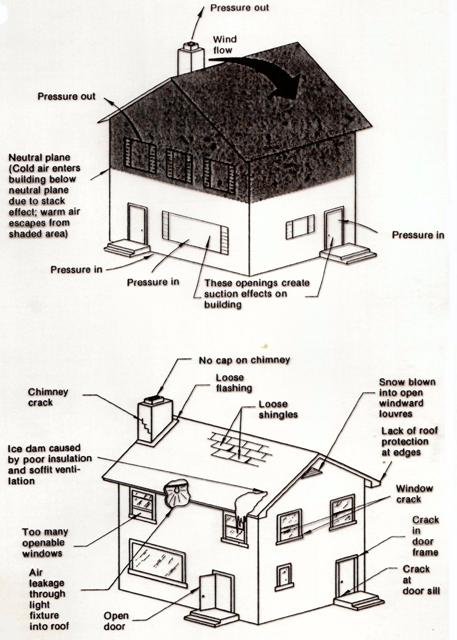
Figure 34: Residential Diagram
Humidity
Humidity is one of the most important topics relative to building design and operation.
Low exterior temperatures in the winter months can contribute to condensation on and in walls and windows and tend to produce low relative humidity indoors. The nature of relative humidity in a building is important to know when determining the proposed exterior wall and roof types.
Relative humidity is a measure of the amount of water vapour present in the air as a percentage of the maximum possible amount at that temperature. The relative humidity outside is typically low in winter and moderate in the summer times.
Figure 37: Dewpoint Graph
Humans are very sensitive to humidity, as the skin relies on the air to get rid of moisture. The process of sweating is your body's attempt to keep cool and maintain its current temperature. If the air is at 100-percent relative humidity, sweat will not evaporate into the air. As a result, we feel much hotter than the actual temperature when the relative humidity is high. If the relative humidity is low, we can feel much cooler than the actual temperature because our sweat evaporates easily, cooling us off.
For example, if the air temperature is 75 degrees Fahrenheit (24 degrees Celsius) and the relative humidity is zero percent, the air temperature feels like 69 degrees Fahrenheit (21 C) to our bodies. If the air temperature is 75 degrees Fahrenheit (24 C) and the relative humidity is 100 percent, we feel like its 80 degrees (27 C) out.
People tend to feel most comfortable at a relative humidity of about 45 percent. Humidifiers and dehumidifiers help to keep indoor humidity at a comfortable level.
From a building operation point of view, humidification systems are added to ensure a consistent level of humidity is maintained. Consistent levels are important to ensure that systems are not affected (computers, machines) and that comfort levels of interior temperatures and pressures are kept constant between the seasons. It is typically required that additional water must be evaporated to raise humidity levels indoors. With the additional water vapour and higher interior pressures of a building during the winter months, water vapour diffuses through interior finishes of walls and ceilings or by air leakage until it encounters cold surfaces and is condensed.
The hidden condensation in roofs, attics, and walls presents far more danger than visible condensation. If surface temperatures are below freezing, ice will occur which can dispense a load of water during thaw. At the worst conditions, up to one pound of frost per square foot of wall or roof area can form in the systems of a building.
Humidity can affect dimension changes in building materials through increased or decreased water vapour contained within the systems. Warm, wet materials will tend to expand while cool, dry materials shrink. In this manner, the operational systems can affect the overall performance of the building. The level of humidity producing a level of water vapour leads to condensation.
Condensation
Condensation is a problem found typically around holes or leakage through the vapour barrier. Most often, the condensation is worst on the leeward side of a building due to wind pressures and on the upper floors due to the stack effect. Condensation is most often found around the cracks and openings in windows, doors, walls and roof systems installations. Venting the wall and attic/roof areas allows vapour to escape the building without creating condensation on any systems.
Condensation occurs when warm moist air meets a cold surface. The risk of condensation therefore depends upon how moist the air is and how cold the surfaces of rooms are. Both of these depend to some extent on how a building is used. In a room with a cold outside wall, the temperature of which falls below the dew point temperature, it is quite normal for condensation to occur predominantly on the lower parts of the external walls and may be confused with rising damp.
Condensation occurs usually in winter, because the building structure is cold and because windows are opened less and the moist air cannot escape.
Condensation which you can see occurs often for short periods in bathrooms and kitchens because of the steamy atmosphere, and quite frequently for long periods in unheated bedrooms; also sometimes in cupboards or corners of rooms where ventilation and movement of air are restricted. Besides condensation on visible surfaces, damage can occur to materials which are out of sight, for example from condensation in roofs.
Condensation typically occurs where humidification has been added by a mechanical system. Condensation is basically an annoyance, reduces visibility, produces cold surfaces and can be psychologically bothersome. Condensation may lead to severe damage of surrounding construction due to materials being wet for long periods of time.
Air movement helps to alleviate the problem by keeping the water vapour from attaching to the wall/roof members. Condensation specifically occurs when air borne vapour encounters a lower temperature member that allows it to adhere to it. The use of thermal breaks in a wall/roof system helps to minimize the possibility of condensation, allowing a higher level of humidity to be present. Thermal breaks are necessary in multiple glazing to allow high room temperatures and humidity.
Window surfaces usually determine the maximum room relative humidity that can be carried without condensation. Window surfaces are easily the most identifiable temperature variable in a wall/roof installation.
Sealants
A seal is intended to prevent the passage of liquids or gases through the space between two components being joined, despite the differential movements between them. Sealants are used to augment the security of the joints on vapour barriers, close openings or joints between different materials and enhance the overlap of materials.
Most joints on the exterior of building require a seal to prevent or minimize the passage of water, water vapour, air or contaminants. Sealants have been considered as plugs for cracks or joints between building components.
Sealants should not be considered as an ideal solution for any situation. They should be installed as an additional safeguard, not the only line of defense.
Specific sealant installations should follow these rules:
· Locate the seal where it has the least critical function.
· Protect the sealant from factors that may cause or accelerate deterioration.
· Calculate the size and nature of movement that will occur at the joint.
· Select the sealant and installation method according to the first three items.
Sealants are one of the prime maintenance items on any building. They are subject to a high variety of temperatures, differential movement and weather deterioration. These factors contribute to a very short lifespan (two years) of sealants when compared to the estimated life span of a building (fifty years or more).
A critical matter to remember relative to sealants is that the cross-sectional area of the sealant bead always remains constant. It is a lot like a piece of chewing gum that gets stretched. There is not any additional material for it to rely on when the joint begins to move. Sealants installed where there is a high degree of separation should be filled to allow for a maximum amount of material during the expansion periods.
Figure 38: Sealant Breakdown
Sealants are one of the few use-specific items on a construction project. There are so many different types and applications that it is critical to ensure the proper type is used in the proper manner. The idea of a general sealant is not one that should be considered.
NEW TEXT DEFINITIONS:
{a listing of new architectural
definitions provided by this component}
APPENDIX 'A'
List of Images
|
Image |
Source |
|
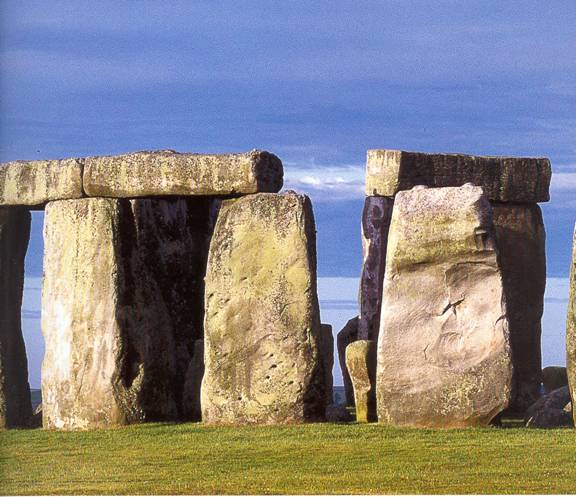
Cover Image: Stonehenge, Salisbury Plain, England (6,000bc) |
Buildings that changed the world,
page 10 |
|
Figure 1: Early Illustration of Steel (1856) |
Architecture – From Prehistory to
Postmodernism, page 466 |
|
Figure 2: Falling Water, Frank Lloyd Wright (1936) |
Architectural Source Book, page 152 |
|
Figure 3: Building Systems |
By Author |
|
Figure 4: A Wide Variety of Available Materials |
Internet Image |
|
Figure 5: Weather and Building |
Internet Image |
|
Figure 6: Wind Force Reactions |
Internet Image |
|
Figure 7: Wind Velocity Tunnel Testing |
Internet Image |
|
Figure 8: Structural Loading Diagram |
By Author |
|
Figure 9: Hurricane Damage, Florida (2004) |
Internet Image |
|
Figure 10: Earthquake Forces, California (2004) |
Internet Image |
|
Figure 11: Action and Reaction Diagram |
Structure and Design, RCSSD Science
Curriculum, page 216, Edited by Author |
|
Figure 12: Force Location Factors |
By Author |
|
Figure 13: Tension and Compression |
Structure and Design, RCSSD Science
Curriculum, page 216, Edited by Author |
|
Figure 14: Concrete Beam Section |
Architecture – From Prehistory to
Postmodernism |
|
Figure 15: Forces acting on an Arch |
Structure and Design, RCSSD Science
Curriculum, page 223 |
|
Figure 16: Arch Construction Sketch |
Architecture – From Prehistory to
Postmodernism, page 117 |
|
Figure 17: Forces on Vaults |
Architecture – From Prehistory to
Postmodernism, page 117 |
|
Figure 18: Wall Systems, Amiens Cathedral |
Architecture – From Prehistory to
Postmodernism, page 240 |
|
Figure 19: Truss System |
Internet Image |
|
Figure 20: Ancient Greek Foundations |
Vitruvius – Ten Books on
Architecture, page 200 |
|
Figure 21: Belled Pile |
By Author |
|
Figure 22: Skin Friction Pile |
By Author |
|
Figure 23: Bell Tower, Pisa Cathedral (1063) |
Buildings that changed the world,
page 69 |
|
Figure 24: Potential Foundation Failure Points |
By Author |
|
Figure 25: Three Types of Foundation Movement |
By Author |
|
Figure 26: Landscaping Plan |
By Author |
|
Figure 27: Solar Orientation |
Canadian Building Digests |
|
Figure 28: Wind Affects |
By Author |
|
Figure 29: Blown in Snow Drifts |
Internet Image |
|
Figure 30: Snow Load Diagrams |
CMHC Wood-Frame House Construction |
|
Figure 31: Hong Kong Bank Building, Shanghai |
Architectural Source Book, page 181 |
|
Figure 32: Expansion Joint for Roof Systems |
By Author |
|
Figure 33: Vertical Air Pressures |
By Author |
|
Figure 34: Thermal Diagrams |
Canadian Building Digests |
|
Figure 35: Insulation Diagrams |
Canadian Wood Construction Manual,
Thermal Insulations |
|
Figure 36: Residential Diagram |
CMHC Wood-Frame House Construction |
|
Figure 37: Dewpoint Graph |
Internet Image, www.gsu.com/edu |
|
Figure 38: Sealant Breakdown |
By Author |
APPENDIX 'B'
Bibliography
Canada Mortgage and Housing Corporation,
Canadian
Wood-Frame House Construction
CMHC Press, Ottawa, Ontario, 1979
Canadian Wood Construction Publications CWC - SP3,
Thermal
Insulation
Canadian Wood Council, Ottawa, Ontario, 1978
Muller, Edward J.
Architectural
Drawing and Light Construction
Prentice-Hall Inc.,
National
Research Council of
Canadian
Building Digests, Numbers 1 through 200
National Research Council Press, Ottawa, Ontario
Regina Catholic Separate School Division No. 81
Structures
and Design
Curriculum Outline, Regina, Sask.
Rowland, Ingrid D. and Thomas Noble Howe
Vitruvius
– Ten Books on Architecture
New York, USA; Cambridge University Press, 1999
Reichold, Klaus & Bernard Graf
. Buildings that Changed the World
London, England; Prestel Press, 2000
Trachtenberg, Marvin & Isabelle Hyman
. Architecture:
From Prehistory to Postmodernism
The Netherlands; Harry N. Abrams, B.V., 1986
Winters, Nathan B
. Architecture
is Elementary
Peregrine Smith Books, Salt Lake City, Utah, USA, 1986